

Appendix A – Abbreviations
Table A1: Abbreviations used in this document.
| AHO | Australian Hydrographic Office |
|---|---|
| AMP | Australian Marine Park |
| AUV | Autonomous underwater vehicle |
| BIST | Built-in Systems Test (Kongsberg specific) |
| BITE | Built-in test environment (Reson specific) |
| BM | Benchmark |
| CD | Chart Datum |
| CTD | Conductivity / Temperature / Depth |
| CRP | Common Reference Point |
| DGNSS | Differential Global Navigation Satellite System |
| DGPS | Differential Global Positioning System |
| DOP | Dilution of Precision |
| GA | Geoscience Australia |
| GDA2020 | Geodetic Datum of Australia 2020 |
| GNSS | Global Navigation Satellite System |
| GPS | Global positioning system |
| HAT | Highest Astronomical Tide |
| HIPP | Hydroscheme Industry Partnership Program |
| ICSM | Inter-Governmental Committee on Surveying and Mapping |
| IHO | International Hydrographic Organisation |
| IMU | Inertial motion unit |
| ISO | International Organisation for Standardisation |
| ITRF | International Terrestrial Reference Frame |
| LAT | Lowest Astronomical Tide |
| LINZ | Land Information New Zealand |
| MBES | Multibeam Echo Sounder (inclusive of interferometric bathymetric swath systems) |
| MHHW | Mean High Water |
| MHWS | Mean High Water Springs |
| MLWS | Mean Low Water Springs |
| MRU | Motion Reference Unit |
| MSL | Mean Sea Level |
| NESP | National Environmental Science Program |
| NM | International Nautical Mile |
| PPK | Post Processed Kinematic |
| PPS | Pulse Per Second |
| QA | Quality Assurance |
| QC | Quality Control |
| ROS | Report of Survey |
| ROV | Remotely operated vehicle |
| RTK | Real Time Kinematic |
| SD | Sounding Datum |
| SIC | Seabed mapper in Charge |
| SMS | Seabed Mapping System |
| SO | Special Order |
| SV | Sound Velocity |
| SVP | Sound Velocity Probe or Sound Velocity Profile |
| SVS | Sound velocity sensor |
| THU | Total Horizontal Uncertainty |
| TPU | Total Propagated Uncertainty |
| TVU | Total Vertical Uncertainty |
| UTC | Coordinated Universal Time |
| UTM | Universal Transverse Mercator |
| WGS-84 | World Geodetic System 1984 |
| XBT | Expendable Bathythermograph |
Appendix B – Glossary
Below are some of the terms used in these guidelines. A more extensive list of hydrographic terms and definitions can be found in Table 2.1.2 of AHO (2018).
% Overlap: refer to the amount of overlap between adjacent swaths. 0% overlap means that the ship tracks are run so that the outer beams of the swath meet the outer beam of the adjacent swath, which is not recommended, 10-20 % overlap is recommended (Figure B1). 100% overlap means that the adjacent ship track is run along the outer beam edge (meeting the required specification) of the previous swath (Figure B2). Refer to section 7.4 of AHO (2018) for more details
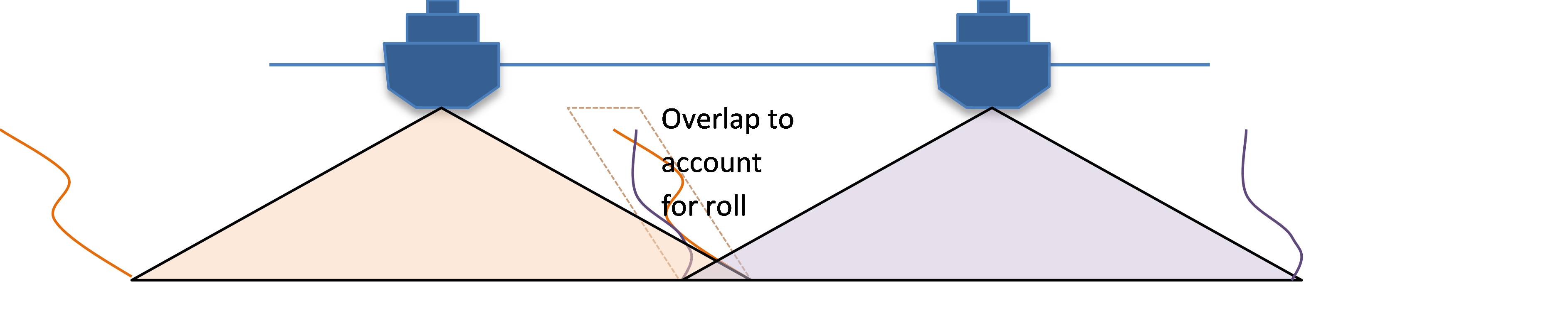
Figure B1 100% swath coverage with 10-20 % overlap to account for ship role and line keeping (AHO, 2018)
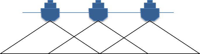
Figure B2 200% swath coverage with 100 % overlap (AHO, 2018)
Blunders: See Error, gross.
Checkline: Sounding lines that are run perpendicular to the main survey lines and used to QA the soundings.
Coverage: portion of the seabed cover by the multibeam swath. 100% coverage refers to 100% of the seabed covered by the swath without any overlap (Figure B1), while 200% coverage refers to 100 % overlap (Figure B2). Partial coverage refers to a seabed coverage that is less than 100%.
Crossline: also known as checkline
Depth: Depth is a vertical distance from a given vertical datum. Depths are derived by MBES from measurements of angles and ranges corrected for environmental factors. Horizontal Position is provided to derived depth by GNSS-Inertial system thus providing an xyz value. GNSS Inertial system derived vertical position from measurements of angular rates and acceleration.
Dimension control: consists of determining the relationship between the measurement sensor and the platform Common Reference Point.
Error: The difference between an observed or computed value of a quantity and the ideal or true value of that quantity.
Error, gross: The result of carelessness or a mistake; may be detected through repetition of the measurement. Also called blunder.
Error, random: remaining uncorrelated noise in the system, or noise, also known as accidental error.
Patch test: A patch test is a specific survey performed prior to principal survey to allow adjustments of the MBES data for parameters such as transducer error (pitch, roll and yaw), and navigation latency. This test is done since the MBES has no reference to external fixed frame of reference (satellite constellation isn’t visible underwater), the MBES receives its “frame” from GNSS-Inertial system. These adjustments are entered in the acquisition software. For patch test patterns see Appendix F.
Seabed backscatter: Defined as the amount of acoustic energy being received by the sonar after a complex interaction with the seabed. Measured as the ratio between the intensity of the acoustic pulse scattered back by the seafloor and the incident intensity, this information can be used to determine bottom type, knowing that the different bottom types “scatter” sound energy differently. The intensity of the backscatter received at the transducer depends on the transmitted source level, the transmission loss (absorption in the water column and geometrical spreading), and the target strength. Many multibeam sonar systems offer two types of seabed backscatter data namely “one-per-beam” backscatter (either beam average or max intensity) and “time series” backscatter. For further information on backscatter refer to Lamarche and Lurton, 2017
Sounding datum: This datum is used while mapping. It is a low-water plane to which soundings are reduced and above which drying heights are given on the Standard Sheet and in other survey records. However, for chart datum, tidal reduction is essential (Figure 3).
Swath system: Current swath sounding systems utilize two differing technologies to achieve bathymetry measurements across a “swath” of the sea floor: 1) Beam forming (multibeam echo sounders), and 2) interferometric or phase discrimination sonars, also known as bathymetric sidescan. Both of these techniques have their merits; however, the same end results are achieved.
Systematic error: see error.
Transit data: Transit data include any data collected outside the survey specific area, e.g. data collected between port and survey area or between sampling sites. In hydrographic terms, this is referred to as passage soundings.
Water Column backscatter: Recently developed multibeam sonars have the capability to record the sonar time series for each beam, which maps the water column in addition to the seafloor. Water column data could be used for direct mapping of fish and marine mammals, the mapping of plumes and vents, the location of mid-water targets, and a wide range of physical oceanographic processes.
Appendix C – Legislation and permitting
Table C1: List of documents relevant to multibeam activities in the Commonwealth waters (defined as 3 nautical miles seaward to the outer boundary of the EEZ, 200 nautical miles). Extracted from Marine Sampling Field Manuals (Przeslawski and Foster, 2018). Similar issues should be considered when working in coastal waters of States and the Northern Territory.
| Activity | Activity Type | Jurisdiction | Responsible Agency | Legislation/Treaty/ Documents | Requirements for approval | Link |
|---|---|---|---|---|---|---|
| Research and monitoring | All activities | Australian Marine Parks | Department of Agriculture, Water and Environment (DAWE) | Environment Protection and Biodiversity Conservation Act 1999 (Cth) (EPBC Act) | Authorisation is required for all zones | https://parksaustralia.gov.au/marine/contact/ |
| Activities with potentially significant impact on a matter of national environmental significance | Commonwealth | DAWE | Australian Marine Park Management Plans EPBC Act |
EPBC Act referral Public consultation, including indigenous stakeholders |
http://www.environment.gov.au/protection/environment-assessments/ http://www.environment.gov.au/epbc/what-is-protected |
|
| All activities | Heard Island and McDonald Islands | DAWE | Environment Protection and Management Ordinance 1987 (HIMI) \ EPBC Regulations 2000 | Permit required | https://www.antarctica.gov.au/living-and-working/travel-and-logistics/cargo-and-freight/types-of-cargo/scientific-samples/environmental-approvals/ | |
| All activities | Antarctica (south of 60°S) | DAWE | Antarctic Treaty (Environment Protection) Act 1980 Antarctic Marine Living Resources Conservation (AMLRC) Act 1981 |
Authorisation and permit required AMLRC Act permit required if carrying out research with respect to marine living organisms in the CCAMLR Convention Area |
https://www.antarctica.gov.au/environment/environmental-impact-assessment-approvals-and-permits// | |
| Interactions with Cetaceans | Acoustic equipment with received exposure level 160dB re 1 µPa2.s for 95% of shot at 1km range (seismic) |
Commonwealth | DAWE | EPBC Act Policy Statement 2.1 | EPBC Referral and comply with Policy Statement 2.1 | http://www.environment.gov.au/resource/epbc-act-policy-statement-21-interaction-between-offshore-seismic-exploration-and-whales |
| Vessel interaction | Commonwealth | DAWE | EPBC Act. Regulations 2000 (Cth) (EPBC Regulations) part 8 | Report death, injury, stranding or entanglement of whales and dolphins to DoEE. Specific requirements for vessels | https://www.legislation.gov.au/Details/F2016C00914 | |
| Interaction with Heritage | Historic Ship wrecks | Continental shelf waters (incl. some areas > 200 nm) | DAWE | Historic Shipwrecks Act 1976 (Cth) | Ship wrecks and relics older than 75 years and lying within protected zones. | http://www.environment.gov.au/heritage/historic-shipwrecks |
| Restricted vessel movement and moored scientific equipment that create navigation hazards | Australian Hydrographic Service AHS Australian Marine Safety AMSA |
Notice to mariners 2-3 weeks prior to survey commences. Vessel to RCC to update NAVAREA X alerts |
https://www.amsa.gov.au/safety-navigation/navigation-systems/maritime-safety-information-database datacentre@hydro.gov.au rccaus@amsa.gov.au |
|||
| Research in the Great Barrier Reef Marine Park GBRMP | Research, except for limited impact research. | GBRMP | Great Barrier Reef Marine Park Authority GBRMPA | Great Barrier Reef Marine Park Act 1975 (Cth) EPBC Act |
Limited impact research may be conducted under a letter of authority issued by an accredited educational or research institutions All other research requires permission | http://www.gbrmpa.gov.au/zoning-permits-and-plans/permits http://www.gbrmpa.gov.au/zoning-permits-and-plans/permits/research-permissions |
| Research around petroleum and other infrastructure | Commonwealth | National Offshore Petroleum Safety and Environmental Management Authority (NOPSEMA) | Sea Installations Act 1987 | Vessels prohibited to go within a safety zone of 500m | http://www.environment.gov.au/topics/marine/marine-pollution/sea-dumping/sea-installations | |
| Accessing areas where a Native Title determination exists | All activities | Commonwealth | National Native Title Tribunal | Native Title Act 1993 (Cth) | Refer to National Native Title Tribunal registers. | http://www.nntt.gov.au/Pages/Home-Page.aspx |
| Activities within Defence Offshore Training Areas or Restricted Airspace | All activities | Commonwealth | Department of Defence (DoD) | Refer to NOTAMs, NTMs and AUSCOAST or NAVAREA X warnings | http://www.hydro.gov.au/factsheets/WFS_Firing_Practice_And_Exercise_Areas.pdf https://www.airservicesaustralia.com/aip/aip.asp https://nationalmap.gov.au/#share=s-wMPX5gwlZcPGccu8ijiVrF4RFIx offshore.petroleum@defence.gov.au ADF.Airspace@defence.gov.au |
|
| Impact on the commercial fishing industry | Activities with potentially significant impact fish stocks or habitat | Commonwealth | Commonwealth Fisheries Association (CFA) | Fisheries Management Act 1991 (Cth) | Consultation | https://www.afma.gov.au/sustainability-environment/petroleum-industry-consultation (List of regional bodies on website) ceo@comfish.com.au |
Laws and regulations regarding multibeam sonar acquisition in State and Territory waters (less than 3 nm from the coast) vary slightly across jurisdictions, but they are generally not restricted or subject to permit requirements, with the exception of:
- Survey undertaken in Marine Protected Areas (for guidance see Marine Protected Areas section above).
- Survey carrying out extractive work (marine biota) or work that could be considered destructive to marine habitats.
- Surveys undertaken across areas with access restrictions (e.g., naval waters, commercial ports, or shipping channels).
- Surveys carried out In New South Wales for the purposes of resource exploration (permission through NSW Resources and Energy - Environment and Planning).
Table C2: Weblinks to state and territory permits
| VIC Research | SA Research | NSW Research | NT Research | TAS Research | QLD Research | WA Research |
Appendix D – Guideline on timeframe for actions
Table D1: Estimated time frame required to perform some of the swath system related tasks. These estimates are to assist in survey planning, but note that they can vary considerably depending on the difficulty or the issues arising from the task performed.
| Action | Timeline to be expected |
|---|---|
| Authorisation/permits from authority | Months |
| Mobilisation, calibration, validation (does not include time to manufacture mounts to fit the system) | 3-5 days |
| Patch test | 2 hrs to 0.5 day |
| Self-system test | 2-5 minutes |
| SVP cast (depends on water depth and device) | 20 min plus deployment time of the SVP, which depends on water depth (based on SVP not XBT device) |
| Crossline | 0.5 day (depends on survey area) |
| Acquisition vs Processing ratio (depends on the quality of the input data and the level of cleaning) | 1:1 to 1:3 |
Appendix E – Total Propagated Uncertainties
Table E1: Sounding Accuracy - Example MBES Total Propagated Uncertainty Estimates to a 95 % CL
| Uncertainty Source | Value | Reference to Accuracy Value for Total Propagated Uncertainty Computation |
|---|---|---|
| Heading (degrees) | 0.05 | (Make/Model) – Manufacturer Accuracy Value |
| Smart Heave (Amplitude %) Real-Time Heave (Amplitude %) |
2.5 5.0 |
(Make/Model) – Manufacturer Accuracy Value |
| Smart Heave (m) Real-Time Heave (m) |
0.025 0.05 |
(Make/Model) – Manufacturer Accuracy Value |
| Roll (degrees) | 0.01 | (Make/Model) – Manufacturer Accuracy Value |
| Pitch (degrees) | 0.01 | (Make/Model) – Manufacturer Accuracy Value |
| Navigation (m) | 0.10 | (Make/Model) – Manufacturer Accuracy Value |
| Transducer Timing (s) | 0.001 | Estimated – 1PPS (Make/Model) |
| Navigation Timing (s) | 0.001 | Estimated – 1PPS (Make/Model) |
| Heading Timing (s) | 0.001 | Estimated – 1PPS (Make/Model) |
| Heave Timing (s) | 0.001 | Estimated – 1PPS (Make/Model) |
| Pitch Timing (s) | 0.001 | Estimated – 1PPS (Make/Model) |
| Roll Timing (s) | 0.001 | Estimated – 1PPS (Make/Model) |
| Offset X (m) | 0.02 | Estimated – (Description of Dimensional Control method) |
| Offset Y (m) | 0.02 | Estimated - (Description of Dimensional Control method) |
| Offset Z (m) | 0.02 | Estimated - (Description of Dimensional Control method) |
| Speed (knots) | 0.10 | Not Applicable |
| Loading (m) | 0.02 | Estimated |
| Draft (m) | 0.05 | Estimated – (Description of measurement) |
| Delta Draft (m) | 0.02 | Estimated - Vessel Dynamic Draft (Squat/Settlement) Calibration |
| MRU Heading Alignment (degrees) | 0.05 | Estimated - Multi-beam Patch Test Calibration |
| MRU Pitch/Roll Alignment (degrees) | 0.05 | Estimated - Multi-beam Patch Test Calibration |
| Tidal Measurements (m) | 0.02 0.02 0.03 0.05 |
(Make/Model) TG – Manufacturer Accuracy Value (Make/Model) Barometer – Manufacturer Accuracy Value Estimated - GNSS Buoy TG calibration Estimated – Accounting for above Contributions |
| Tidal Zoning (m) | 0.10 | Estimated - Co-Tidal Model |
| SVP Profile Measurement (m/s) | 0.02 0.50 |
(Make/Model) – Manufacturer Accuracy Value Estimated - Temporal and Spatial Variation |
| SVP Surface Measurement (m/s) | 0.017 | Make/Model) - Manufacturer Accuracy Value |
| Sonar Measurement | MBES Device Models File |
Appendix F – Patch test
The figures below shows the pattern to use for the patch test of a MBES system with one (Figure F1) or two (Figure F2) sonar head configurations.
For backscatter calibration see section 4.3.2

Figure F1: Proposed line pattern for single head sonar patch test

Figure F2: Proposed line pattern for dual-head sonar patch test
Appendix G – IHO Standards
Table G1: IHO standards for hydrographic surveys (S-44). Read in conjunction with document (IHO, 2008). These are presently in review by the IHO.

Table G2: HIPP standards for hydrographic surveys (AHO, 2018)

Appendix H – Records templates
The following appendix provides suggested templates for records that should be produced during a seabed mapping survey. These templates can also be downloaded on the AusSeabed website.
H.1 Mobilisation, calibration and validation report
The following link provides you with the template.
H.2 AusSeabed minimum required metadata
Below is a table with specific field definitions and examples for each metadata field expected to accompany data submitted to AusSeabed in order for AusSeabed to assume custodianship of, and to exclusively publish the data. The fields specified are considered a minimum set that can be extended to include fields outlined in section 2.3.1.3, but should not be deviated from, replaced, or altered. Note that on submission it is only required to provide the Field column and the associated survey metadata, the other columns in the table are provided for illustrative purposes only.
Table H1: Required Metadata for data submitted to AusSeabed
| Category | Definition | Fields | Specific Field Definitions | Example Data |
|---|---|---|---|---|
| General | Basic information about the data package being submitted. | Survey title (full) | A short phrase or sentence describing the dataset. In many discovery systems, the title will be displayed in the results list from a search, and therefore should be human readable and reasonable to display in a list of such names. | MH370 Phase 1 150m Bathymetry datasets |
| Survey ID | The ID assigned to the survey, relevant especially when an ID may be how the survey is more widely referenced. | GA-4421, GA-4422, GA-4430 | ||
| Abstract | A paragraph describing the dataset, analogous to an abstract for a paper. | “On behalf of Australia, the Australian Transport Safety Bureau (ATSB) is leading search operations for missing Malaysian airlines flight MH370 in the Southern Indian Ocean. Geoscience Australia provided advice, expertise and support to the ATSB to facilitate bathymetric surveys … [for full abstract visit http://pid.geoscience.gov.au/dataset/100315] | ||
| Lineage | Information about the events or source data used in constructing the data specified by the scope or lack of knowledge about lineage. | “link-to-lineage-statement” OR | ||
| Full text: | ||||
| Lineage can be complex to record, so can be actively linked within a metadata record either to a file within the dataset being submitted or to a hosted location where the lineage statement may be found. If neither of these options are preferred, a full narrative may also be provided. | “The MH370 Search bathymetry Surveys, GA-4421 GP1483 was acquired by the Australian Government through ATSB/GA on-board the MV Fugro Equator from the 05th of June to the 30th of July 2016, GA-4422 through the Chinese Navy Vessel Zhu Kezhen 872 from the 3rd June to 31 August 2014 and from the 5th January to the 30 April 2015 for the MV Fugro Supporter………” | |||
| Contact for the Data | Information that is related to contacts for the data | Data Owner | . The person and/or organisation that owns the submitted data for the purpose of empowering AusSeabed to act as a custodian | Commonwealth of Australia |
| Custodian | The person and/or organisation that accepts, archives and disseminates the data | Commonwealth of Australia | ||
| Point of Contact | The person and/or contact details for initiating contact regarding the data | Commonwealth of Australia (Geoscience Australia) | ||
| clientservices@ga.gov.au (Manager Client Services) | ||||
| Cnr Jerrabomberra Ave and Hindmarsh Dr GPO Box 378, Canberra, ACT, 2601, Australia | ||||
| Call 1800 800 173,02 6249 9960 | ||||
| Collecting Entity | The organisation that was responsible for collecting the data being described. | Australian Transport Safety Bureau (ATSB) | ||
| Citation | Information that is collected to ensure appropriate credit is assigned for the data being provided, and ensuring the data’s intended use of the data is clear. | Attribution Licence (citation) | Statement of attribution that must be included whenever the data being provided is distributed/redistributed or used by another organisation. | 2017. MH370 Phase 1 150m Bathymetry datasets (GA-4421, GA-4422 & GA-4430). Geoscience Australia, Canberra. http://pid.geoscience.gov.au/dataset/100315 |
| Legal Constraints | Restrictions and legal prerequisites for accessing and using the resource or metadata | Creative Commons Attribution 4.0 International Licence | ||
| http://creativecommons.org/licenses/ | ||||
| Access Constraints | Details of any constraints that are not determined under the licence constraints regarding the access to the information being provided. Access constraints are applied to assure the protection of privacy or intellectual property, and any | As per licence | ||
| special restrictions or limitations on obtaining the resource or metadata | ||||
| Use Constraints | Details of any constraints that are not determined under the licence constraints regarding the use of the information being provided. | As per licence | ||
| Country (of data ownership) | Country of the owner of the data. | Australia | ||
| Survey Positioning Data | The information provided in the positioning data provides for both an overview of the survey’s coverage, and the primary coordination reference system that was used to collect/prepare the survey data. | Survey area (general) | Plain English description of the location of the survey. | Indian ocean approximately 1100nm off the coast of Perth Australia. |
| Survey bounding box coordinates | The detailed coordinates of the survey. This may be provided in a variety of formats, however full positioning information is required. | 78.00, -42.00, 116.00, -12.00 | ||
| Coordinate reference system - Bounding Box | The coordinate reference system used to define the survey bounding box. | "WGS 84 / UTM zone 44S (EPSG:32744)","WGS 84 / UTM zone 46S (EPSG:32746)","WGS 84 / UTM zone 47S (EPSG:32747)","WGS 84 / UTM zone 48S (EPSG:32748)","WGS 84 / UTM zone 49S (EPSG:32749)","WGS 84 / UTM zone 50S (EPSG:32750)" | ||
| Coordinate reference system - Survey Data | The coordinate reference system used for data collection. | "WGS 84 / UTM zone 44S (EPSG:32744)","WGS 84 / UTM zone 46S (EPSG:32746)","WGS 84 / UTM zone 47S (EPSG:32747)","WGS 84 / UTM zone 48S (EPSG:32748)","WGS 84 / UTM zone 49S (EPSG:32749)","WGS 84 / UTM zone 50S (EPSG:32750)" | ||
| Reference System | The finer details of the reference system used for data collection. | Geodetic datum of the survey | The reference datum of the data collected | WGS 84 |
| Horizontal Datum | The horizontal reference datum for data collection | UTM | ||
| Vertical Datum | The vertical reference datum for data collection | MSL | ||
| Survey Configuration | The configuration of the survey as it ran. | Instrument type | The type of instrument used to capture the data. Suggested values are: | Multi-beam Sonar |
| - Multi-beam | ||||
| - Single-Beam | ||||
| - Bathy LiDAR | ||||
| - Airborne Imagery | ||||
| - Satellite | ||||
| - Side-Scan | ||||
| - Sub-Bottom profiler | ||||
| Sensor type | The type of sensor used to collect the data being provided. | EM2040 | ||
| Sensor Frequency | Frequency at which the survey was conducted. This may be provided as multiple values based on the sensor’s capabilities. | 200-400kHz | ||
| Platform type | The platform hosting the instruments and sensors used to collect the data. | Ship, AUV | ||
| Platform Name | The name of the platform used to collect submitted data | RV Investigator |
H.3 Survey log sheet templates


H.4 Report of Survey template
The following minimum template has been modified from AHO AH68 Survey Summary Template, which can be found in full here. A full Report of Survey format can be found in IHO publication C13. Guidance on Confidence Levels and Error Ellipse scaling is contained in ICSM (2014a), uncertainties from IHO publication S-44 or by contacting the Bathymetric Data Assessment Section at the Australian Hydrographic Office on 02 4223 6500.
Introduction
| Survey Title and ID | Locality |
| Survey Authority | Survey Sponsor/Custodian |
| Surveyor in Charge and qualification | Date this Survey Summary was completed |
| Start Date of Survey | End Date of Survey |
| Survey Platform/Vessel Name | Survey Platform/Vessel Name |
| Purpose of the Survey | |
Horizontal Control
| Soundings are on the following datum (WGS84 preferred but not essential) | |
| Datum | |
| Spheroid | |
| Projection and Zone | |
| Was the positioning system validated? | |
| Were laybacks applied? | |
| Estimated horizontal accuracy of soundings at 2 Sigma (95%) confidence level (Calculations can be included as an attachment. Don’t know? Enter “Not Known”) | |
Vertical Control
| Tides Applied | |
| Soundings Datum | |
| Tide Station 1 Details | |
| Benchmark (BM) used and Datum connection | |
| Geoid details if using GPS tides | |
| Tide Station 2 Details | |
| Benchmark (BM) used and Datum connection | |
| Geoid details if using GPS tides | |
| Tide Station 3 Details | |
| Benchmark (BM) used and Datum connection | |
| Geoid details if using GPS tides | |
| Tide Model comments (if applicable) | |
| Were soundings corrected for draught? | |
| Were the soundings corrected for sound velocity? | |
| Estimated vertical accuracy of soundings at 1.96 Sigma (95%) confidence level (Calculations can be included as an attachment. Don’t know? Enter “Not Known”) | |
Shoals and Dangers
| This section seeks comments on any features that may be dangerous to surface navigation. (Comments as required. General location and depth references, pictures, screen dumps, etc. will assist. Has a Hydrographic Note or Danger to Navigation Report been submitted?) |
Wrecks
| This section seeks comments on any wrecks detected during the course of survey. (Comments as required. General location and depth references, pictures, screen dumps, etc. will assist.) |